As mentioned in my earlier post, I purchased one of the relatively inexpensive CNC engraver / routers from ebay. The mechanical build quality seems good, and overall I'm satisfied with the purchase. I reverse engineered a set of schematics from the two boards in the controller box (see previous post).
One hassle with these controllers is that they are designed to be driven from a PC's parallel port (with EMC2 or Mach providing the gcode to step and direction translation). Who has a PC with a parallel port these days? USB-to-LPT converters don't work well for this application, as the gcode enterpreters like Mach rely on detailed control of the parallel port, which can't be readily accomplished with a USB peripheral.
One obvious solution is GRBL. It is a gcode interpreter written to run effectively on an Arduino board (328P version, please). Obviously none of the Arduino boards are going to provide the right connectorization for directly connecting to the CNC controller box, so I started designing a carrier board which would marry an Arduino Nano to the appropriate DB25 connector to connect to the box.
After a bit of thought, I decided it would be simpler to build a GRBL compatible Arduino board in a DB25 connector shell form factor, and the (not so cleverly named) usb2db25 project was born.
 |
| front |
 |
| back |
 |
| with case back |
 |
| in case |
The strange form factor of the board was designed to maximize the internal real estate of a DB25 connector shell. The mini USB connector is available at the back of the connector, and a 1/8" stereo jack is available on the side to provide two discrete inputs for STOP and CYCLE START switches.
In addition to the step and direction signals, the board supports limit / homing switches for all three axes, PWM spindle control, and a probe signal input. Basically all of the features present on the stepper controller board of the CNC control box are usable via the usb2db25.
As the schematic is pretty much stock Arduino Nano, the standard versions of GRBL run without modification. When attached to a PC via USB, the unit shows up as a serial port.
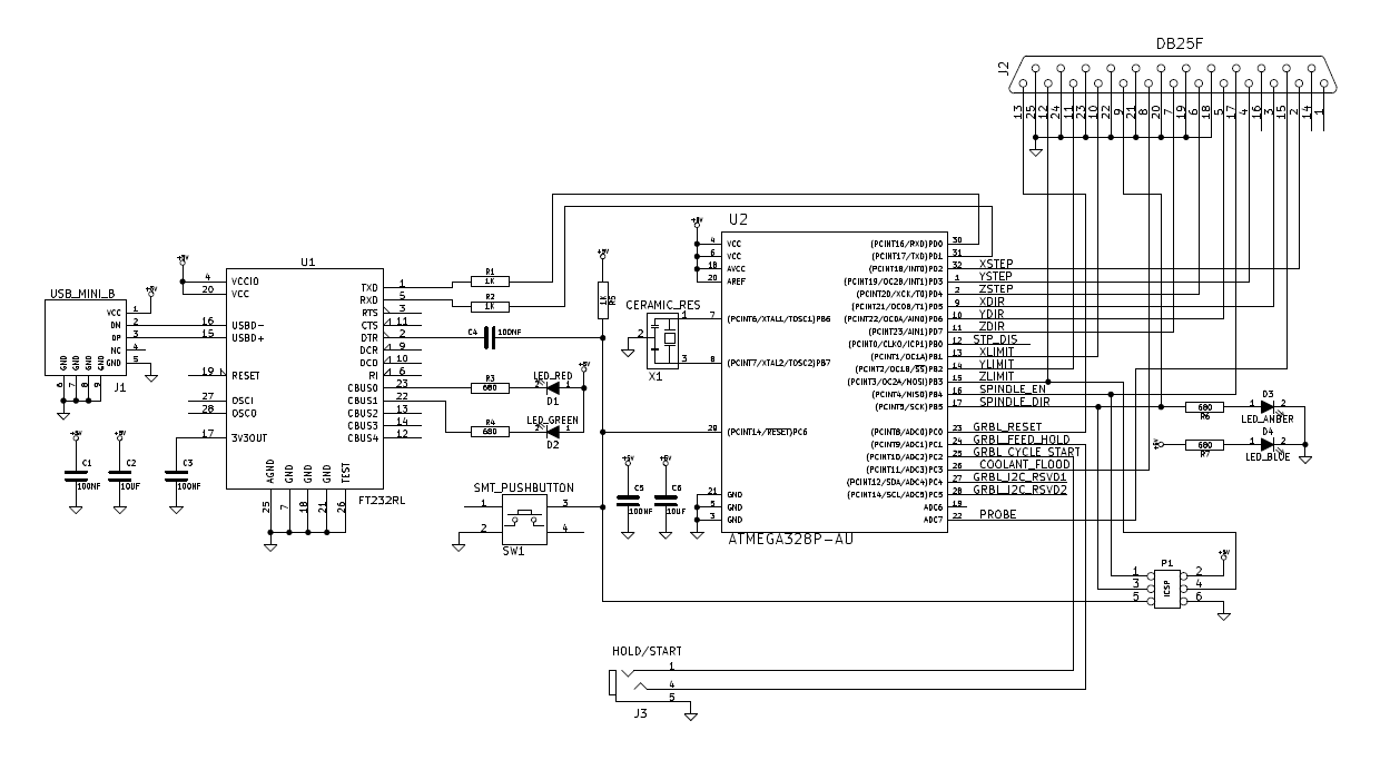 |
| usb2db25 schematic |
You can obtain GRBL from GitHub here.
The one thing I haven't done yet is to drill some small holes in the DB25 connector shell to allow visibility of the LEDs on the board.
Because it runs GRBL, the need for a package like EMC2 or Mach is completely eliminated, and you can just pipe gcode directly to the usb2db25. Using this unit and the limit switches I added to the CNC engraver / router, I have a substantially more capable tool.
UPDATE: Based on some requests, here are the gerbers for the pcb: usb2db25 gerbers

